ENGINEERING
Positive Room Pressurization
(1)Positive Room Pressurization for ESS, E-House, RIE
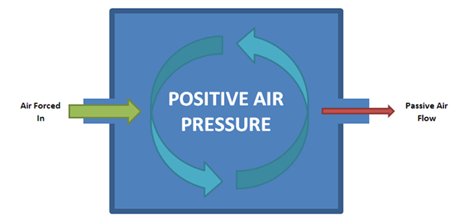
Positive pressure is a pressure within a system that is greater than the environment that surrounds that system. Consequently, if there is any leak from the positively pressured system, it will egress into the surrounding environment. This is in contrast to a negative pressure room, where air is sucked in.
Use is also made of positive pressure to ensure there is no ingress of the environment into a supposed closed system. A typical example of the use of positive pressure is the location of a habitat in an area where there may exist flammable gases such as those found on an oil platform or laboratory cleanroom. This kind of positive pressure is also used in operating theaters and in vitro fertilisation (IVF) labs.
Hospitals may have positive pressure rooms for patients with compromised immune systems. Air will flow out of the room instead of in, so that any airborne microorganisms (e.g., bacteria) that may infect the patient are kept away. This process is important in human and chick development.
Positive pressure, created by the closure of anterior and posterior neuropores of the neural tube during neurulation, is a requirement of brain development. Amphibians use this process to respire, whereby they use positive pressure to inflate their lungs.
(2)Room Pressurization Calculation
Require condition :
Roompressurization = +ve 15Pa
ACH = 6
Caluculation :
ACH = (V x 60) / Vol
Where Vol = room volume (cu ft.) & V = total outlet air flow (cfm)
V =(ACH x Vol) / 60
Which is V = (6 x 16000) / 60
V = 1600cfm
* 1,600cfm must be removed from the room to achieve min 6 Air Change Per Hour (ACH).
Where V = RA + EA = 1600cfm
Given condition, EA : RA = 1 : 9
EA = 160cfm
RA = 1440cfm
According to require condition, the roome must be in poritive (+ve) pressurized.
So, Supply air (SA) must be more than total outlet air flow (V). SA > V.
SA > 1600cfm
But what should be the additional air flow to pressurize the room up to 15Pa.
(3)Room Pressurization Calculation Video
(4)Calculation Result ( Pressurization Air Calculation )
Room Size : L 14m x W 12.0m x H 4.0m, Room Pressure : +25Pa
| Room | Leakage Area Ratio |
Press AP (Pa) |
Direction | Wall Width (m) x Height (m) |
Leakage Area (m2) |
Over Pressure (L/S) |
Safety Factor 10% (L/S) |
Total Pressurization Air Volume |
|---|---|---|---|---|---|---|---|---|
| Excitation Cubicle PKG |
||||||||
| 0.000052 | 25 | Ceiling | 14.0 x 12.0 | 0.0087 | 91 | 60 | 662L/S (39.72 CMM) (2383 CMH) (1402 CFM) |
|
| 0.000170 | 25 | N | 14.0 x 4.0 | 0.0095 | 100 | |||
| 0.000170 | 25 | E | 12.0 x 4.0 | 0.0082 | 96 | |||
| 0.000170 | 25 | S | 14.0 x 4.0 | 0.0095 | 100 | |||
| 0.000170 | 25 | W | 12.0 x 4.0 | 0.0082 | 96 | |||
| 0.000052 | 25 | Floor | 14.0 x 12.0 | 0.0087 | 91 | |||
| Door (w) 1.8m | 1000x0.7x0.0144 x R(2x25/1.2) x1 |
16 | ||||||
| Door (s) 0.9m | 1000x0.7x0.0072 x R(2x25/1.2) x 1 |
32 | ||||||
| 602 | 60 |
-
1.The effective air leakage area (in square centimeters) is based on a pressure difference of 4 Pa and CD=1
Estimate areas per units are based on values found in the literature.
Based on chapter 16.15 of ASHRAE Handbook Fundamentals (SI, 2009) -
2.
Abbreviations: (P) is Wall or Floor Partition.
-
3.
Calculation formula of Leakage air flow through Door.
1) V = 1,000 x a x A x √(2 x ΔP/d ) [L/S]- Where : V : Leakage air flow
- a : Flow coefficient, 0.7 will be applied
- A : Actual area of the threshold gap (m2)
- ΔP : Room pressure difference (Pa)
- d : Density of standard air at 20 deg. C (1.2 kg/m3)
2) Actual area of the threshold Gap of 4 mm- For Double door 1.8 m width A = 1.8 x 2 x 0.004 = 0.0144
- For Single door 0.9 m width A = 0.9 x 2 x 0.004 = 0.0072
-
4.
10% of over pressure shall be applied as the safety factor (S.F) for the other openings or miscellaneous.
1) Flow area of each room will be calculated using a following formula.- • AW = SW x KW (m2)
- • AF = SF x KF (m2)
- Where : AW: Wall leakage area
- SW : Exterior wall area
- KW : Exterior wall leakage area ratio (0.17×10⁻³)
- Stairwell wall leakage area ratio (0.11×10⁻³)
- AF : Floor leakage area
- SF : Floor area
- KF : Floor leakage area ratio (0.52×10⁻⁴)
2) Over Pressure air of pressurized room will be calculated using a following formula.- • QWA = Σ (0.839 x AW x △P1/2 ) x 1,000 (L/s)
- • QFL = Σ (0.839 x AF x △P1/2 ) x 1,000 (L/s)
- • QS = QWA + QFL (L/s)
- Where : △P : Pressure difference across flow path
- QWA : Wall leakage air (L/s)
- QFL : Floor leakage air (L/s)
- 1,000 : Conversion factor
* Base on Chapter 52 of ASHRAE Handbook Applications (SI, 2007)